Introduction
Magnetism is a physical phenomenon on which many applications rely. It is the basis of not only electric motors and actuators, but also plays an important role in electrical circuits.
Magnetic Field
The magnetic field $B$ describes the total magnetic field within a material. It is a function of the materials permeability, which is analog to a material’s conductivity for electrical circuits. A magnetic field can be produced by either “free” currents or “bound” currents denoted by $H$ and $M$, respectively. “Bound” currents implies that the electrons are bound to their corresponding atoms but orbit in the same direction, producing microscopic currents, as it occurs in permanent magnets (PM). Similarly to current in electrical circuits, the magnetic field always forms a closed loop path and cannot dissipate.
Hopkinson’s Law
The reluctance is the magnetic analog to resistance in electrical circuits. The only difference is that a resistance dissipates energy, while reluctance stores it. The magnetomotive force (MMF), Reluctance and the Flux relate through Hopkinson’s law:
$$\mathcal{F}=\mathcal{R}\Phi$$
Magnetic Circuit
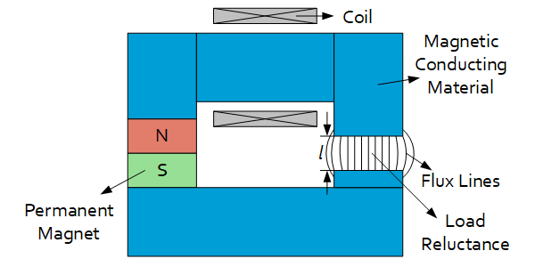
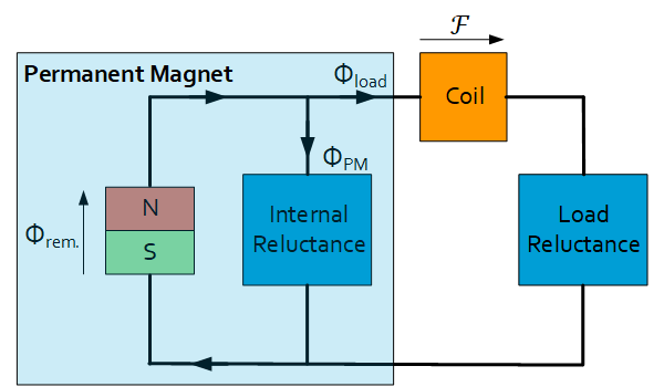
Similarly to electrical circuits, a magnetic circuit can be created with Reluctances Flux and MMF sources. The following figures illustrate a setup with a PM, a coil and a Load Reluctance and its corresponding magnetic circuit. A PM can be modelled as a constant flux source with parallel internal reluctance. The coil is modelled as a constant MMF source. Applying Kirchhoff’s circuit laws, all quantities in the magnetic circuit can be solved.


| Description (electrical analog) | Formula |
|---|---|
| Magnetic Permeability (electrical conductivity) | $$\mu$$ |
| Length of Magnetic Path | $$l$$ |
| Cross-sectional Area of Magnetic Path | $$A$$ |
| Number of Turns of a Coil | $$N$$ |
| Magnetic Field Strength | $$H$$ |
| Magnetization | $$M$$ |
| Magnetic Field (Current density) | $$B=\mu\left(H+M\right)$$ |
| Magnetic Flux (Current) | $$\Phi=BA$$ |
| Reluctance (Resistance) | $$\mathcal{R}=\frac{l}{\mu A}$$ |
| Magnetomotive Force (MMF) (Voltage) | $$\mathcal{F}=NI=\oint{H\ \partial l}=\mathcal{R}\Phi$$ |
| Faraday’s Law of Inductance | $$\mathcal{E}=-N\frac{\partial\Phi}{∂t}$$ |
| Lorentz Force | $$F_{Lorentz}=I\ l\times B$$ |
| Reluctance Force | $$F_{Reluctance}=\frac{1}{2}\frac{\partial}{\partial l}\left(R\Phi^2\right)$$ |
Magnetic Energy
The magnetic energy stored in a magnetic circuit can be derived by using Faraday’s law of inductance to calculate the electrical energy required for a coil to create that magnetic field:
$$E_{electric}=\int_{0}^{T}{UI\ \partial t}=\int_{0}^{T}{N\frac{\partial\Phi}{\partial t}I\ \partial t}=\int_{0}^{\Phi}{\mathcal{R}\Phi\ \partial\Phi}$$
$$E_{field}=\frac{1}{2}\mathcal{R}\Phi^2=\frac{1}{2}\frac{\mathcal{F}^2}{\mathcal{R}}$$
The equation above is generic and also applies to PMs.
It has to be noted that for a magnetic field produced by a coil with a constant MMF, a change in reluctance also results in energy transferred to and from the coil as evident by the equation above.
Reluctance Force
The reluctance force is deduced by deriving the energy stored in the magnetic field by displacement of the load reluctance according to:
$$F=-\frac{\partial E}{dl}$$
Due to the large permeability of the magnetic conducting material, its reluctance is assumed zero. For a magnetic circuit driven by a coil, the MMF is assumed constant. The general force equation is given by:
$$F=\frac{\Phi_{load}^2}{2A_{load}\mu}$$
For the case that only one flux or MMF source is present, the reluctance force is given by:
$$F_{coil}=\frac{\mathcal{F}^2}{2A_{load}\mu}\left(\frac{1}{\mathcal{R}_{pm}+\mathcal{R}_{load}}\right)^2$$
$$F_{pm}=\frac{\Phi_{rem}^2}{2A_{load}\mu}\left(\frac{\mathcal{R}_{pm}}{\mathcal{R}_{pm}+\mathcal{R}_{load}}\right)^2$$
Lorentz Force
The Lorentz force acts perpendicular to a moving charge moving through a magnetic field. The force acting on a wire is given by:
$$F_{Lorentz}=I\ l\times B$$
