Introduction
Standard buckling equations are commonly known. However, through FEM-development, analysis of post buckling behavior is possible and now elements in post buckling state can be used in construction design to the benefit of the constructions’ performance.
Negative stiffness effect
A buckled leaf spring comprises a negative stiffness in the lateral direction for the range:
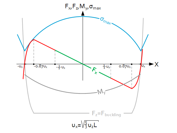
$-0.87u_x<x<0.87u_x$
With $u_x=\sqrt{\frac{5}{3}u_zL}$
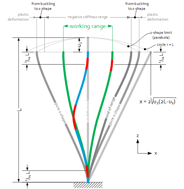
Beyond this range the buckling is ‘transforming’ into a pure s-mode bending which is reached at: $x=\pm\ u_x$. With moving back the buckling does not re-occur. In combination with manufacturing tolerances-effects, the (JPE-) working range is:
$-\frac{1}{2}u_x<x<\frac{1}{2}u_x$
Buckling force
The buckling force can be considered constant after buckling and can be determined with:
$F_{buckling}=4\pi^2\frac{EI}{L^2}$
Linear stiffness
The vertical (longitudinal) stiffness is zero. And as said, laterally it comprises a negative stiffness. The y-stiffness is similar to the transverse stiffness of a unbuckled leaf spring:
$C_x=-44,4\frac{EI}{L^3}$
$C_y=\frac{Etb^3}{L^3}$
$C_z=0$
Stress
The maximum (Von Mises) stress is located in the ‘bending poles’ of the buckling shape which are on $\frac{1}{14}L$. For the location of the maximum stress, see the red spots in the picture. An approximation of the stress:
$\sigma_{max}=53\ \cdot\frac{Et}{L}\cdot\frac{u_z}{L}\cdot\sqrt{1-\left(\frac{\left|x\right|}{u_x}\right)^3}$
(1st order estimate: please verify with FEM or consult JPE)
Thus $\sigma_{max}$ decreases when moving in lateral direction: the buckling ‘gets relieved’. Maximum compression can be approximated with:
$u_{z-max}=\frac{\sigma_{allowable}L^2}{53Et}$
(1st order estimate: please verify with FEM or consult JPE)
Reaction Moment
Obviously, to maintain the shape as depicted a moment at the top must be applied, this is qualified in the graph. This moment can be approximated with:
$M_y=-3.2\ E\cdot t^3\cdot\frac{u_z}{L}\cdot\sqrt{1-\left(\frac{x}{{0.87u}_x}\right)^2}$
(1st order estimate: please verify with FEM or consult JPE)
(negative implies pointing out of the sheet with right-hand-rule)
Graphical layout
Necessary forces for buckling and lateral shift
Rules of thumb
- $C_x$ is not affected by $u_z$ or by $u_x$
- $F_z$ is not affected by $u_z$ or by $u_x$
- $\sigma_{max}$ is affected with $u_z$ and by $u_x$
- The range of motion can be increased with $\sqrt L$ or $\sqrt{u_z}$
- The stress is at the ‘bending pole’ (see graphical layout);
- movement towards the “belly” at $\frac{1}{14}L$
- movement away at $L-u_z-\frac{1}{14}L$