Introduction
A force sensor can be obtained from a well-matched combination of a known stiffness and a displacement or strain sensor. Typically commercially available force sensors have been designed for high stiffness (> 1e6 N/m) to measure large forces (>> 10 N) which makes them unsuitable for applications requiring mN or even sub-mN resoluti0n. For such an application JPE designed a custom force sensor with a resolution of 0.1 mN and a range of ±3 N.
Excellent performance
- Large range vs large resolution: dynamic range = 6e4 using laser interferometry displacement sensor
- 0.1 mN resolution due to low stiffness
- Low sensor drift / capable of DC force measurement
- Possibility to implement 2nd sensor (Eddy Current) for absolute force sensing.
Concept
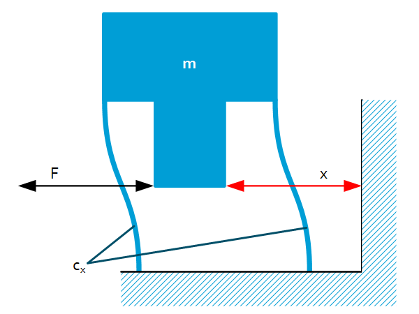
Rigid mass $m$ is connected to the fixed world via 2 parallel leaf springs. 2 Parallel leaf springs are well-known for a play-free linear guidance that comprise the following stiffness:
$C_x=2C_{x\ }=2\frac{12EI}{L^3}$
A contactless displacement sensor measures the displacement of $m$ in relation to the fixed world as a consequence of the applied force. The sensor used is a laser interferometer with nm resolution. With a stiffness of $1e5\ N/m$, the resolution becomes $0.1\ mN$. In the application in which the force sensor was used, $1e5\ N/m$ was the lowest acceptable value (in relation to the dynamics of the application) but if a lower stiffness of the leaf springs is acceptable even better resolutions can be reached.
Stiffness calibration
Manufacturing tolerances influence the stiffness. E.g. the stiffness changes with the leaf spring thickness to the 3rd power. Therefore the sensor is calibrated using precision weights; first the moving mass $m$ is determined with the use of a precision weight ($m_2$) and the resulting 2 eigen frequencies ($\omega_1$ and $\omega_2$): $m=\frac{m_2}{\left(\frac{\omega_1^2}{\omega_2^2}-1\right)}$. Hereafter the force cell is placed in multiple angular configurations (with and without extra weights) to determine the stiffness curve ($F$ vs. $x$) with $F=mg\cdot \sin(\alpha).$
Linearity
The derived stiffness-linearity of the 2 parallel leaf springs is within 2%.
Parasitic displacements
When the 2 parallel leaf springs move in $x$, the sag ($z$) in height is: $z=\frac{3}{5}x^2/L$. In this particular case the maximum sag is $1.8 \mu m$ at end-of-stroke (which is negligible).
Overview

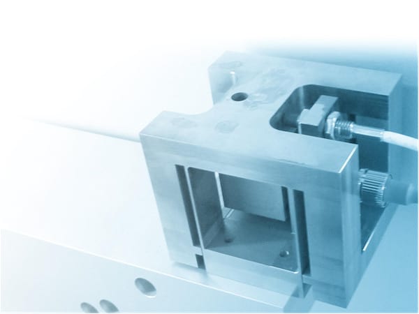
Integrated sensor

Features
- Monolithic part
- Matching materials for sensor and monolith for temperature stability
- Vacuum compatibility
- Force input at L/2 of the leaf springs for pure linear guidance (no parasitic normal forces)
- Symmetry over the width eliminating parasitic forces and moments
- Mechanical end-stops preventing the leaf springs from exceeding the yield stress ($\sigma_{0.2}$)
- Volume claim: 50 mm x 50 mm x 50 mm
