Introduction
Motion systems are generally designed to be operated with feedback design control. A common way in industry to design such a controller is carried out by loop shaping, i.e. manually design the open-loop frequency response and interactively evaluate the results on the basis of closed-loop responses (e.g. sensitivity function). Benefits of this approach:
- It can be carried out directly on frequency-response data
- Design is intuitive and results can be mode robust
- Resulting controllers are (generally) of low-order
General designs steps ( = Rules of thumb)
The generic structure of a motion controller consists of a basic PID structure with a low pass filter. However, for the design steps presented, the controller is somewhat differently structured.
1. Determine the desired bandwidth of the system. This can be based on the disturbance specifications of the system.
- Bandwidth = $f_{bw}$
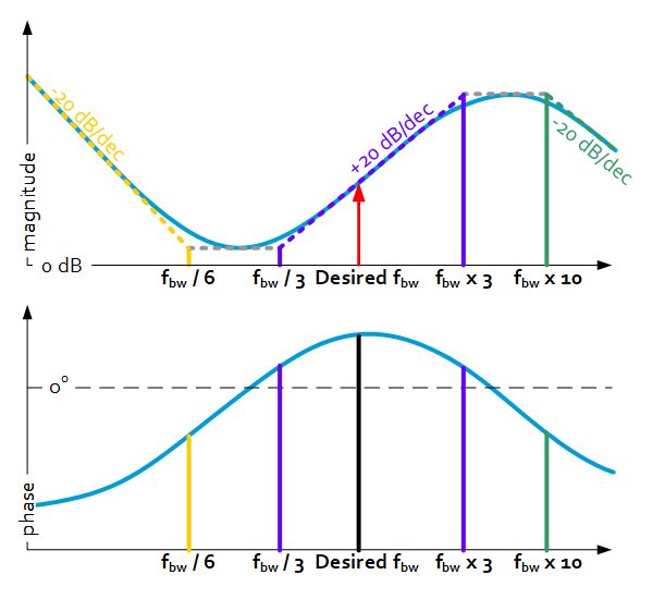
2. Add a lead-lag filter around the bandwidth frequency, such that phase lead is optimal at bandwidth.
- Choose lead at 1/3 x bandwidth, lag at 3 x bandwidth
3. To avoid high-frequency amplification of dynamics and to reduce sensor noise amplification, a lowpass filter is added.
- Choose the low-pass frequency at 10 x bandwidth
4. If zero DC error is desired, an integral action should be added.
- Choose the integral cutoff frequency at 1/6 x bandwidth
5. Calculate controller gain K, such that.
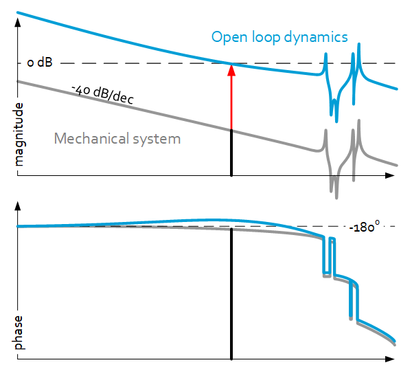
- Choose K such that 0dB crossing of the OL-system is at $f_{bw}$

Delay through digital implementation will give additional phase, which increases for low sample frequencies.
- Sample-frequency 50 x bandwidth
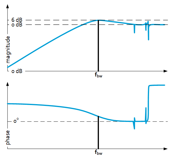
Resulting controller will have a sensitivity peak of 6dB.
Additional design considerations
Use additional filters, e.g. notch filters to deal with parasitic dynamics; see other Precision Point sheet.
Typical frequency response

Controller

Sensitivity

