| Load case | $L_b$ | Load case | $L_b$ |
|---|---|---|---|
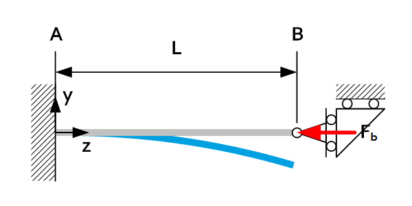 | 2L | 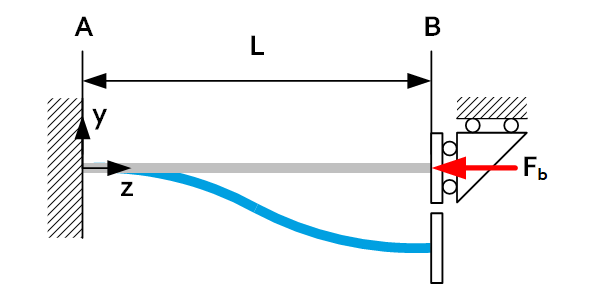 | 1L |
 | 2L | 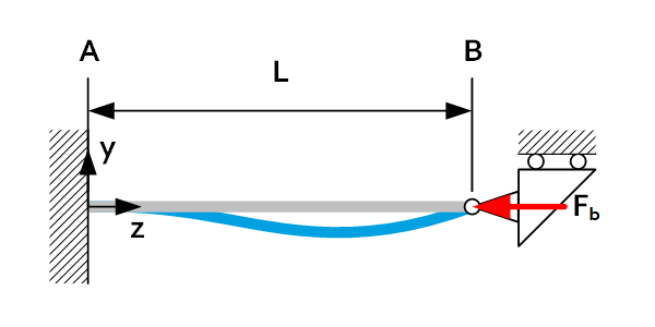 | 0.7L |
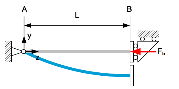
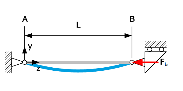 | 1L | 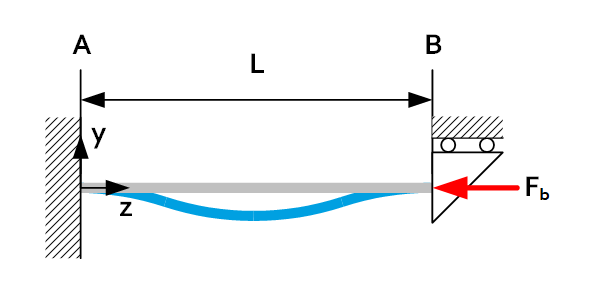 | 0.5L |
| Load case | $F_b/L_b$ | Load case | $F_b/L_b$ |
|---|---|---|---|
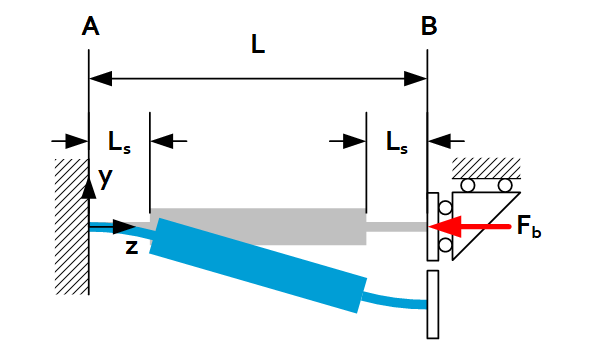 | $$F_b=\frac{\pi^2EI_{xs}}{4L_sL}$$ or $$L_b=2\sqrt{L_sL}$$ |  | $$F_b=\frac{\pi^2EI_{xs}}{L_s^2}$$ or $$L_b=L_s$$ |
| Load case | $L_b$ | Load case | $L_b$ |
|---|---|---|---|
| 2L | | 1L |
| 2L | | 0.7L |
| 1L | | 0.5L |
| Load case | $F_b/L_b$ | Load case | $F_b/L_b$ |
|---|---|---|---|
| $$F_b=\frac{\pi^2EI_{xs}}{4L_sL}$$ or $$L_b=2\sqrt{L_sL}$$ | | $$F_b=\frac{\pi^2EI_{xs}}{L_s^2}$$ or $$L_b=L_s$$ |