Introduction
This XYZ positioning stage is specifically developed for cryogenic applications where high resonance frequencies are required. Furthermore this stage can be used in a scanning mode for small movements around a given set point.
Pro’s & Con’s
- Operational down to 1 K
- High resonance frequency
- Sub nanometer resolution scanning mode
- Play/backlash free
- Antimagnetic materials
- Scanning motion in closed loop enabled by high mechanical resonance frequency
- Parasitic displacements ($R_x, R_{y}, Z$)
- Small piezo drift in open loop operation
- $X, Y, Z$ coupling in motion control
Concept
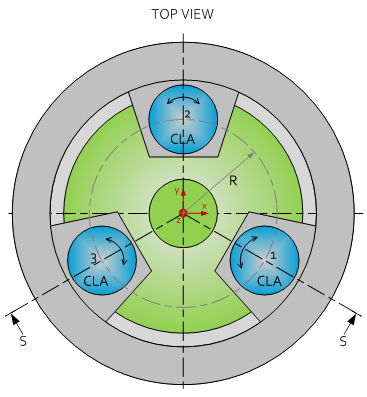
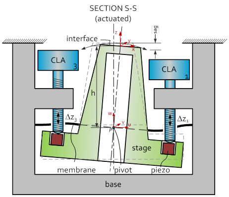
The concept of the high resonance stage is depicted below. The key element of the concept is that the XYZ motion of the stage is created by three actuators in a parallel configuration, where other stages typically make use of stacked actuators. In this way the resonance frequency is increased over an order of magnitude.
Effectively the XYZ motion is created by a tip/tilt/piston motion in relation to a relatively distant ($h$) pivot location $P$. The pivot location is enforced by an internal membrane which fixes the XY position of a given point $P$ at the center axis of the stage. The sag which is a typical parasitic motion in such a mechanism can easily be compensated by a Z motion.
The stage is driven by three independent CLA’s (Cryogenic Linear Actuators), which operate in Z-direction and are placed at a radius $R$ in an equi-triangular configuration. The CLA’s can make a stepping motion with a typical speed of a few micron/sec, with a resolution in the range 1…5 nanometer (depending on working temperature) for ‘coarse’ positioning.

Scanning mode
Each CLA has a piezo element on top. This enables an analogue positioning (<< 1 nm resolution) of the stage within the stepping resolution of the CLA. Furthermore the piezo elements enable a dynamic XYZ (scanning) profile of the stage. Given the high mechanical resonance frequency of the mechanism this mode can be operated at high bandwidth.
Working range
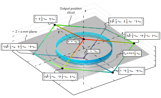
The $X, Y, Z$ working range of the mechanism based on the CLA´s inputs $∆z_1, ∆z_2, ∆z_3$ is described by the following relations.

The working range as function of $\Delta z_{CLA}$, $R$ and $h$ is visualized by the following graph. It’s actually a deformed cube with one of the diagonals coincident with the Z-axis.

It is obvious that XY verses Z range can be exchanged. The relation is straight forward proportional.
- At $z = 0 mm$ the maximum circular XY range is $\frac{h}{R}\cdot z_{CLA}$
- At $z = z_{CLA}$ the maximum circular XY range is $0 mm$
A practical tradeoff for a dominant XY output motion is: - 25% Z-range → $\pm\ 0.25\cdot z_{CLA}$
- (1-25%) XY-range → $\pm\ 0.75\cdot\frac{h}{R}\cdot z_{CLA}$

