Introduction
This sheet provides a design of parallel leaf spring guidance with adjustable stiffness from positive to negative, to benefit its application.
Concept
A parallel leaf spring guidance is a linear guidance which comprises no play and its (relatively low) stiffness is well predictable (see Precision Point sheet: 2 Leaf springs in parallel). A buckled leaf spring comprises a lateral negative stiffness (see Precision Point sheet: Buckling phenomena) and a longitudinal constant force. This negative stiffness can be used to reduce, compensate or even over-compensate the stiffness of the 2 Leaf springs in parallel.
Guidance stiffness
The resultant force in x-direction is a simple addition of the forces resulting from the positive and negative stiffness (subscript P and N, respectively):
$C_x=C_P+C_N=24\frac{E_PI_P}{L_P^3}-44.4\frac{E_NI_N}{L_N^3}$ with $I_{P/N}=\frac{1}{12}w_{P/N}\cdot t_{P/N}^3$
Range of Motion (RoM)
The parallel leaf spring guidance incorporates a parasitic z-displacement which is:
$z=\frac{3}{5}\frac{u_x^2}{L_P}$
If configured as depicted, the buckling distance $u_z$ is influenced with this to: $u_z-z$. This reduces the RoM of the system to (empirical determined):
$u_{xmax}=29\sqrt{15\ }\xi\sqrt{u_z\frac{L_N}{\xi}}$ with $\xi=\frac{L_P}{10000L_P+7569L_N}$
Beyond this range the buckling transforms into a pure s-mode bending and with moving back this buckling does not re-occur. To take into account manufacturing and assembly tolerances, the (JPE-) working range is:
$-\frac{1}{2}u_{xmax}<u_x<\frac{1}{2}u_{xmax}$
Buckling force
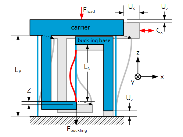
Between the carrier and the fixed world a leaf spring gets buckled, such that its constant longitudinal force is a ‘pull-down’ force to the carrier, as depicted. This way, the parallel leaf spring guidance is under compression, a proper load for these leaf springs. Avoid a pull-up force to the carrier, it cannot be guaranteed that the guidance leaf spring will move in s-shape. A (minor) drawback is that the external load on this carrier is limited.
$F_{buckleP}=8\pi^2\frac{E_PI_P}{L_P^2}$, $F_{buckleN}=4\pi^2\frac{E_NI_N}{L_N^2}$
$F_{load}<\frac{1}{3}\left(F_{buckleP}-F_{buckleN}\right)$
Schematic overview
Manufacturing and tolerances
Typically; 2 leaf spring in parallel (functioning as a linear guidance) are manufactured with wire EDM to have a monolithic part. The leaf springs of the guidance can be reinforced as described in the Precision Point sheet: 2 Leaf springs in parallel. Keep in mind that this does not hold for the buckled leaf spring.
Manufacturing (and assembly) tolerances are of influence to the behavior of the total system. The similarities are:
$C\sim t^3\sim\frac{1}{L^3}$
The thickness-tolerance w.r.t. the thickness itself is typically in the order of 10%, while the length-tolerance w.r.t. the length is of the order <1%. Therefore the system is typically more sensitive to thickness variations.
- 10 % thickness variation ≈ 30 % stiffness variation
- 10 % length variation ≈ 30 % stiffness variation